The Hotspur Chronicles
by Hew of Kilraag
m.k.a. John Rose - Sackville, New Brunswick, Canada
music: Dance of the Knights from Sergei Prokofiev's Romeo and Juliet

|
|
|
|
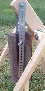
(time passes) Yay! - I was digging around in the basement of the house I had bought last winter, and found two pieces of steel railway rail. One was about 8 cm long, and another piece of heavier gauge rail was about 30 cm. The longer one (shown here) is about 9 or 10 kg. They already had holes through the thin upright part of the rail. |
|
|
|
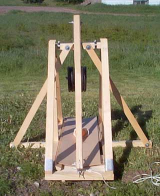
| Closeup of axle support: When I was building it, I left the horizontal axle support cross beam (nominally 2"x"2", actually 36x36 mm) in one piece, until the outriggers, A-frames, and axle posts were cut and assembled. I cut a groove for the axle to sit in along the top by running it several times over the blade of a table saw, with the blade barely clearing the top of the table. I cut the centre section (thickness of beam plus 2 cm clearance) out of the cross beam at the last moment. The outrigger angle supports pass on either side of the vertical axle support posts. Bolting them towards the middle of the cross beam provides support for the axle while permitting a payload of up to 30 cm wide to pass through below. This feature was inspired by a photo of a much larger trebuchet, posted by Ron Toms to the Catapult Message Board. (See Ron's post.) What it does not prevent is horizontal bending, which is what did happen when I was using a 360:1 CW/payload mass ratio. I solved that by increasing the axle diameter from 5/16" to 1/2". Of course this meant drilling out the axle holes in the beam again. |
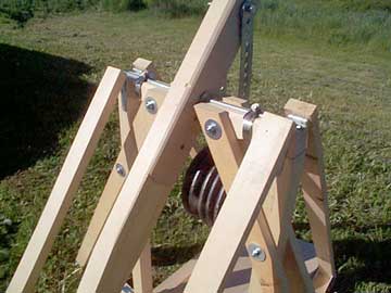 The pipe clamps are good enough to keep the axle from shifting around, and they make it easy to dismantle for transport, or for changing to different arm ratios. In this photo, it's set for a 5:1 arm ratio.
The strap hinges at the tops of the angled A-frame braces allow the braces to be folded in towards the vertical axle support post, when stowing it away. |
|
|
|
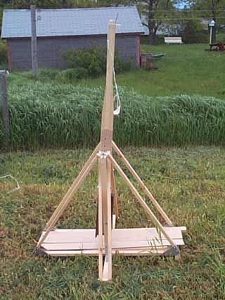 |
June 5, 2002 Initial field trials of trebuchet "Hotspur" went as well as could be expected. I was getting about 20-23 meters with a tennis ball. The trough is two pieces of masonite, simply taped together for a hinge, and either side is elevated by two scrap pieces of 1x2. Eventually I'll glue a strip of rubber or canvas between them like a piano hinge, and cut out some wedge-shaped supports. I left the sling a bit long (until I figure out the optimum length), with excess rope ends tucked up with a series of half-hitches, just to keep them from tangling. I've shortened the release pin since this photo was taken. The pin started out life as a pegboard hook. The main beam axle holes are intentionally off-centre, so that when it is cocked (with the throwing arm tip to the left, in this photo) the majority of the beam is above the axle, for strength. Here I've assembled it for a 5:1 beam ratio. |
|
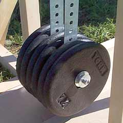
June 8, 2002 More good fortune. I found set of barbells for Cdn$10.00 at a yard sale, with six 7.5 pound weights (total of approximately 20.5 kg) - more than I'll ever need for a trebuchet of this size. Here they are with all six of them on the CW hangers - two on the left, two in the middle, and two on the right. My idea for using these straps for hangers seems to be working out. |
|
|
|
|
 |
With this configuration I was able to drop a tennis ball onto the driveway or the patch of grass next to this side of the concrete steps at the top of the photo.
That distance worked out to about 29-32 meters. I measured it very scientifically, counting the paces to the first bounce and multiplying that number by 0.88.
I had to keep shortening the sling length (to about 80% of the throwing arm length) and straightening out the release pin (to about 10 degrees?) because it was spiking the ball into the tall grass about 10-20 meters out.
A camcorder would have been handy for analyzing the release, but I suspect that the high CW/payload ratio (about 360:1) was causing the throwing arm to rotate to the ideal release angle too quickly for the sling to whip around to the angle where it will slip off the release pin. Shortening the sling would be like a figure skater pulling their arms in close to their body during a spin.
July 22/2002 - Some new info: I found a rule of thumb posted by "phsstpok" on the Catapult Message Board, which I'll call "phsstpok's Rule" ... Here is a rough guideline for HCW machines. Multiply the beam ratio by twenty. Divide your counter weight by the result and that will give a good starting point for your missle weight. By that reckoning, I should be throwing payloads about 200 g. |
| June 16, 2002 (Father's Day - definitely a day for "guy stuff") I just made a new pouch. The old version had ropes passing through a casing sewn into either side of the pouch, allowing for easy adjustment of sling lengths. Unfortunately that design would allow too much curvature, especially for small heavy payloads like rocks, some of which would not be released at all. This pouch used less canvas. The dark blue stuff is bias tape sewn on to keep the raw edges from fraying. The D-rings are heavy gauge copper wire with the hidden ends overlapped and soldered. I chose a thinner nylon cord for a sling. The payload shown here is an official road hockey ball. They have a bit more mass than a tennis ball (tennis balls are 57 g. and these hockey balls are 66 g), but are water-proof and smooth. They don't bounce as much as tennis balls do, either. |
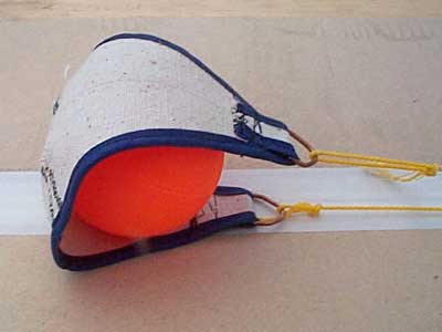 I was getting about 35-40 meters with the hockey ball and the new pouch.
- July 22, 2002 - I've created a new page just for construction details on the old and new pouch designs.
I was getting about 35-40 meters with the hockey ball and the new pouch.
- July 22, 2002 - I've created a new page just for construction details on the old and new pouch designs.
|
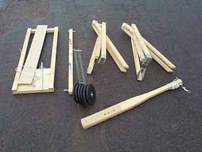 |
Hotspur dismantled and ready for travel in the trunk of a car. The two axle supports (upper right) can be made more compact by taking out the bolt that passes through the outrigger braces and vertical axle posts, but this state was good enough when nothing else was in the trunk. |
Email me at: hew@spamBgone.northernelectric.ca (I'm sure you can figure out
which part to remove from the address. I just don't want to make it easy for
spambots)
Jump up to my medieval index.