The ACME Desktop Trebuchet®
|
[cue music: "Sunrise" from Also
Sprach Zarathustra]
|
|
|
|
[scroll down very slowly, after music starts playing] |
| Spec |
Metric
|
Imperial
|
| Axle height above desktop |
20.4 cm
|
8"
|
| Axle height above bottom of trough |
18.7 cm
|
7 3/4"
|
| Total beam length |
31.2cm
|
12 5/16"
|
| CW axle to main axle |
7.6 cm
|
3"
|
| Main axle to throwing arm tip |
22.9 cm
|
9"
|
| Beam ratio |
3:1
|
|
| Base and trough length (wood components) |
28 cm
|
11"
|
| CW hanger length |
5.7 cm
|
2 1/4"
|
|
CW mass old (6 square washers, 1/4" threaded rod, two washers, and two nuts) |
393 g |
13.9 oz. |
| sling length |
22.9 cm
|
9"
|
| payload masses (optimum, as calculated using phsstpok's Rule*) for new lead counterweight) | 13.2 grams | 0.466 oz. |
|
Range average (wooden bead) The uneven ground that the treb was fired from may account for the unusual differences in the ranges. On earlier trials I was able to get it to land in a small cardboard box about 4 out of 5 times. |
7.65 m
|
25 '1"
|
| Alternate names that were considered |
|
|
| Product is not effective on |
Roadrunners
|
|
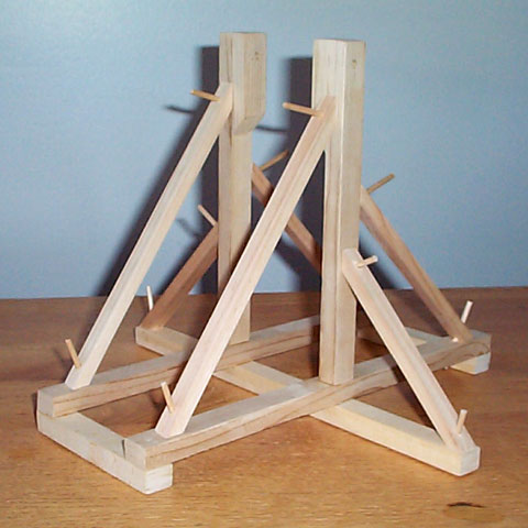
This one is nominally a "1 foot" model, designed and built as a birthday present for my son, Duncan Rose, in July 2002. On the day of his 22nd birthday, I was able to get it to the stage where I had the stain and shellac on, and only needed a sling, pouch, and trigger. At least he got to see it operate with a come-away sling
Construction photo - major components pegged and glued. The trough came later.

The beam and all of the frame timbers are pine, cut from scraps left over from building my first trebuchet, Hotspur. It helped to have access to an electric joiner planer, a table saw, a compound mitre saw, a drill press, etc.
The pegs were cut from a 1/8" dowel, and glued in with Bondrite "Sand-N-Stain Woodworkers Glue", which is supposed to take a stain better than regular carpenters' glue. It took some fancy clamping to keep the timbers in place while I drilled the holes. Afterwards, I sawed the tops of the pegs off with a little hacksaw.
As I mentioned before, I got the beam and counterweight built, and put a stain and shellac on the frame and beam, but got stumped as to how I wanted to do the trigger, sling, and pouch. Then, the bag of parts (including the beam, axle, CW, CW hangers, and miscellaneous hardware) disappeared for many months and the project stalled while the frame sat collecting dust.
Update: April 8, 2003 C.E. (A.S. XXXVII)
|
Yay! -- I found the arm, axle, and counterweight assembly. they were buried in a plastic bag in the laundry room. This was the screen test photo, before the sling and pouch were made. It also shows the old counterweight made out of large square washers. It was as far as I got last year, and I had demoed it then with a come-away sling‡. |
Now to get to work on the pouch...
|
blue grid lines are 1/5 inch apart |
I happened to have some sample swatches of leather, which looked to be about the right size. I cut off one corner with an X-Acto knife, folded it, cut the other corner, opened it up and folded it the other way, and then cut the corners on the other end. I cut a slit about 1/4 of the width in one side, overlapped it to see how much of a V I wanted, then enlarged the slit to a V-cut. Next I folded it and cut the other notch to match (moere or less). This leather tended to stretch under the knife, so it doesn't look perfectly symmetrical. It didn't help that the nylon cutting board was slippery. |
 |
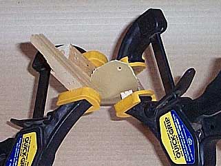
I took two of the triangular pieces from the corner cuts, and glued them (Lepage's "Bond Fast™" - a generic non-toxic white glue) like a patch over the notches, then clamped them between small scraps of wood at an angle, so that they only press on the triangular patches. I didn't want to clamp straight across the two sides because it would probably just flatten the pouch and defeat the purpose of the notches. I kept it clamped for 30 minutes, which is what they rcommended for wood. Man, I love those Quick-Grip clamps. |
 |
Here's what it looks like from the edge. Just a little bit of "dish" to it. Note that I glued the suede sides together. It seemed like a good idea at the time. Maybe it would absorb the glue better than the smooth sides? |
Update May 4/03
 |
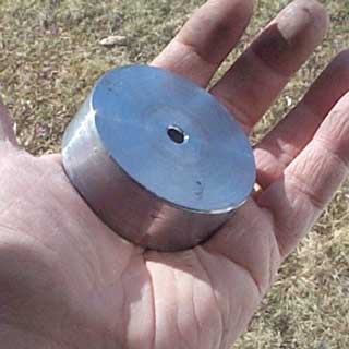
I scored 3/4 of a gallon of discarded lead wheel balancing weights for free (thanks to "Ben's Esso", Sackville) and managed to melt some of them down. I poured it into the bottom half of a Coke can, and then turned it in a lathe just to pretty it up a bit, and to drill a 1/4" hole in the middle. By the time I cut off the rough parts and drilled it, it ended up 62 mm diameter by 24 mm thick. |
|
scanned at 200% |
I found a book in the Mount Allison University library, which had an illustration for a hook that was used to haul down the arm of an onager and as the trigger. - The cord (40-pound test braided nylon fishing line) at
the top is a loop hanging from the tip of the throwing arm. The chief advantage of this slip-hook system is that the lanyard may be used from either side of the frame. Also, it falls out of the way so that there is little danger of it catching in the sling or pouch I fashioned this one out of (I think) 16 gauge annealed steel wire. You get a lot of it for a few bucks, and it looks vaguely like wrought iron. The wire portion is 40 mm long. The curvature of the hook determines the amount of pull required to release the arm. I doubt I would want to use this for an onager (for safety reasons), but it seems suitable for small ("tennisball" class) trebuchets as long as you use heavier gauge wire (such as coat-hanger wire) or a thin rod. |
| Original illustration from The Crossbow†, by Sir Ralph Payne-Gallwey, BT. |
May 11, 2003 - Finally finished and delivered.
 |
This is the sketch for the new (grey suede) pouch. It doesn't show the patches for the V-notches. The notch angle hould have been a bit bigger too, because the result was still a bit too flat for some payloads. I made it narrower than the yellow pouch, but I think it should have gone down to 3 cm wide. I have no idea why I wrote "60%", where I meant "60°". |
 |
Diplomacy failed. The terms of surrender were not satisfactory. We shall provide transportation back to the castle. |
What I would have done differently, if I knew then what I know now:
For the next update - I hope to have a complete list of dimensions of all of the components.
-o-0-o- Footnotes -o-0-o-
* phsstpok's Rule: mass
ratio = 20 * beam ratio
where beam ratio is the length of throwing end of
the beam divided by the length of the counterweight end of the beam
and mass ratio is the counterweight mass divided by
the payload mass.
This rule of thumb was posted by user "phsstpok" to the Catapults Message Board, in this thread - http://web.trebuchet.com/boards/view.php?site=trebuchet&bn=trebuchet_catapults&key=1021357935
I recently had an epiphany as to exactly why there is no point to increasing counterweight mass beyond a certain point, unless you increase the payload and/or the beam ratio. Until I make up a separate page explaining it, here's the discussion I started about it on the Cat Mess Board.
† The full title is actually The Crossbow - Medieval and Modern - Military and Sporting - Its Construction, History & Management - With A Treatise On The Balista and Catapult Of The Ancients And an Appendix On The Catapult, Balista & The Turkish Bow by Sir Ralph Payne-Gallwey, BT., in 1903. Published by The Holland Press, London. ISBN 0-946323-14-3.
‡
Come-away Sling
A sling that is simply a single cord attached to the payload, and a
small ring to go over the throwing arm's release pin. It comes away
with the payload when you fire it. Very useful for trying out different
pin angles, counterweight masses, and sling lengths. Also useful for
hurling payloads that don't easily lend themselves to being put in a
pouch, such as automobiles and major household appliances.
Back to Hew of Kilraag - Medieval Stuff