This is my plan for a rotor that may be cut from squares of fabric and, with the aid of a spreadsheet, be modified to use any number of panels in multiples of four. I got the idea from the Spinsock plan that The Kitemonger published, particularly in how the vents in the leading edge (which provide the spinning action) are designed. It is the difference in lengths of the two unsewn edges that form the turbine-like vents. Some spinning bols also use this feature, around the inner opening.
The idea was to keep the "spin" component, and eliminate the "sock" or bol. Other requirements were that the template be simple to describe, that it not waste any fabric, it must be expandable (in the sense of being able to design it with more panels), and that the sewing be very simple (i.e. compared to, say, a Catherine's Wheel).
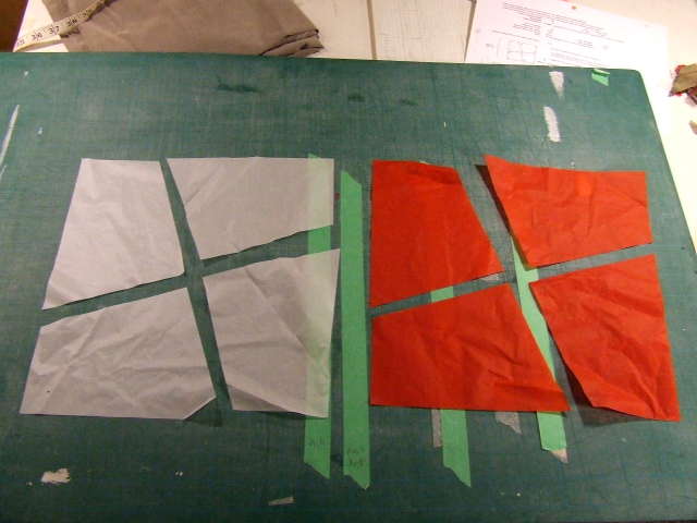
I soon hit on the idea of cutting up squares of ripstop nylon into 4 identical quadrilaterals (instead of the usual triangles). It's a tiling pattern. The two cuts across the middle of the squares are made at an angle, almost an "X", so that inspired its name of "X-Squared". Here is a partial screenshot of the simple drawing that I made for the spreadsheet:
It isn't necessary to make a cutting template, as such, since it's simple enough to mark the ends of the two cutting lines directly on the edges of the fabric squares with a ruler, and cut with a straightedge.
The angle of the "X" cut determines the difference in lengths of sides AB and CD, which not only determines the size of the vent opening, but also whether the whole thing makes a nearly flat bol, or a deeper cone shape. In my spreadsheet, I set it up so that you enter an offset, AB as the percentage of the full length of one side of the square, then enter the number of squares (to be cut into four pieces each) and it calculates the angle of the sides of the finished rotor and the over all diameter. Here was the tricky part - For a given offset percentage (or angle of the "X" cut), increasing the number of squares results in a wider but shallower finished rotor. I found that small changes in the offset resulted in dramatically different angles. I also found that changing the offset also affects the overall size because lengthing the AD dimension directly increases the diameter of the ring. It also makes the ring proportionally thinner.
For the prototype I wanted to end up with sides that were about 45° from the plane of the trailing edge, which appears to be a typical angle for the sides of a bol. I chose to use two squares that were 30 cm on a side (because I had scraps about that size handy), an offset value of 0.320, which yielded sides that were 44.26° up from a flat surface. Close enough. That offset value of 0.320 times square size of 30 cm gives the dimension AB = 9.6 cm. That was enough information to start drawing a template, since the point surrounded by the "C"s is always in the exact centre of the square. Actually, though, the angle of the sides in my prototype may not be 44.26° because some of the width was taken up by the hem, which I didn't allow for in the calculation.
Some values I tried in the spreadsheet were as follows:
(all using 30 cm squares)
2 squares, offset = 0.320, gave AB = 9.6 cm, angle of sides = 44.26°, inner diameter = 38.2 cm, outer diameter = 51.95 cm (This is what I used for the prototype. It actually came out to about 48 cm outer diameter, due to the 1 cm folded hem width.)
3 squares, offset = 0.365, gave AB = 10.95 cm, angle of sides = 45.06°, inner diameter = 57.3 cm, outer diameter = 72.77 cm
4 squares, offset = 0.3915, gave AB = 11.75 cm, angle of sides = 45.11°, inner diameter = 76.39 cm, outer diameter = 92.97 cm
I chose the values of offset by trial and error, until I got an angle close to 45°. Generally, as the value of offset is increased (up to 0.50 max ) the the cut panels approach a square shape, and the more cylindrical it becomes. Smaller values of offset give a shallower rotor, and if the entered offset is too small, it gives an error.
Something I'm not sure of yet is whether or not large numbers of squares make it much more difficult to have it come out right. I'll have to try a couple of calculations and see if small errors in cutting and sewing, or even seam allowances, would "magnify" changes in the angle dramatically for, say 10 squares, giving 40 cut panels to sew together.
Here is the spreadsheet itself - x-squared_rotor.xls - try playing with it, and see what you get. Bear in mind that it gives only rough approximations of dimensions of the finished rotor. It does not, for instance, have any way of including seam or hem allowances. (suitable for OpenOffice, the native Mac version NeoOffice, or Excel)
Meanwhile here are some pictures of the 2-square / 8-panel prototype to give you the gist of it.
Two squares, after cutting.
The inner hem with a leach line sewn into it, to connect the panels together.
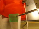
I sewed a leach line into the outer hem as well. I did not bother hemming the vent edges, since the ripstop nylon was hotcut, and this is just a prototype. For the outer hem only, I decided to snip off this little corner bit that would otherwise end up getting sewn to the previous panel. (This was not necessary for the inner hem.) The bridle lines will go between each panel on the outer hem, simply tied around the connecting leach line, which is partly why I didn't want that extra corner bit interfering.
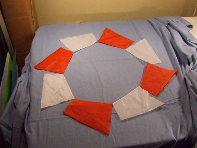
Inner and outer hems completed, and all 8 panels joined. Not the baggy sides of the vents. Just for fun, I picked it up, turned it upside-down and dropped it onthe floor As it fell, it began to spin, so I knew it would probably work.

All that was left to do was to tie on 8 bridle lines to the outside edge, between each panel, and attach them to a swivel. I cut four lines to 3 meters, doubled for 8 lines 1.5 meters long. The outer diameter of the rotor is about 50 cm, so I just used the "3 times diameter" rule of thumb. The 8 bridle lines go on the outer (or leading) edge only, tied to the outer leach line connecting each panel.
Never mind that it was midnight and freezing outside. There was enough wind to test it in the back yard and get a few photos.
Even a light breeze (about walking speed) would make it spin. If the wind picked up at all, it would spin fast enough for the panels to blur. Fortunately, the camera flash "froze" it. It is spinning clockwise here.

Maybe it's not as elegant (yet) as an f-stop bol or a Catherine's Wheel, but by golly, it works, and it spins fairly fast, and with little pull (at least at this size). I'd like to try a larger, shallower one. I'd also like to try stringing several in series, each rotating opposite to the one before it. It would probably work just as well with spikes or streamers sewn onto each panel. We'll see.
Something else to try would be to rotate the cut panels by 90 degrees, joining corners A to B, and C to D, resulting in a smaller diameter but (hard to find good words to describe it) thicker rotor. It might look a bit nicer, more substantial. The spreadsheet would then have to be modified to calculte the angle of the sides for this configuration, and so obtain a different value of AB for the desired angle.
Here's a 35 second video of it, in daylight: x-squared_daytime_test.m4v - 640x360, 29.97 fps, 6.7 MB. That link starts a download in my system, rather than showing up in a browser window.
The same video, different format: x-squared_daytime_test.mov - 320x240, 1.2 MB. It starts playing in a new browser window on my system. Because this one ended up with a frame rate of only 14.98 fps, it has that weird "reversing wagon wheel" aliasing effect, and it looks as if it's not turning or even spinning backwards at times.
I started a thread on the kitebuilder.com discussion forum about it. I go by the user name of "planish" there.